
This provides a function to generate a virtual defect in OK template images by using the training result acquired in the Developer. The [Auto] tab provides the function to automatically generate as many images as desired, following the defect generation region set by users on the reference image. Users who want to generate defects using various training results can generate defects in multiple products by adding sub-tabs.
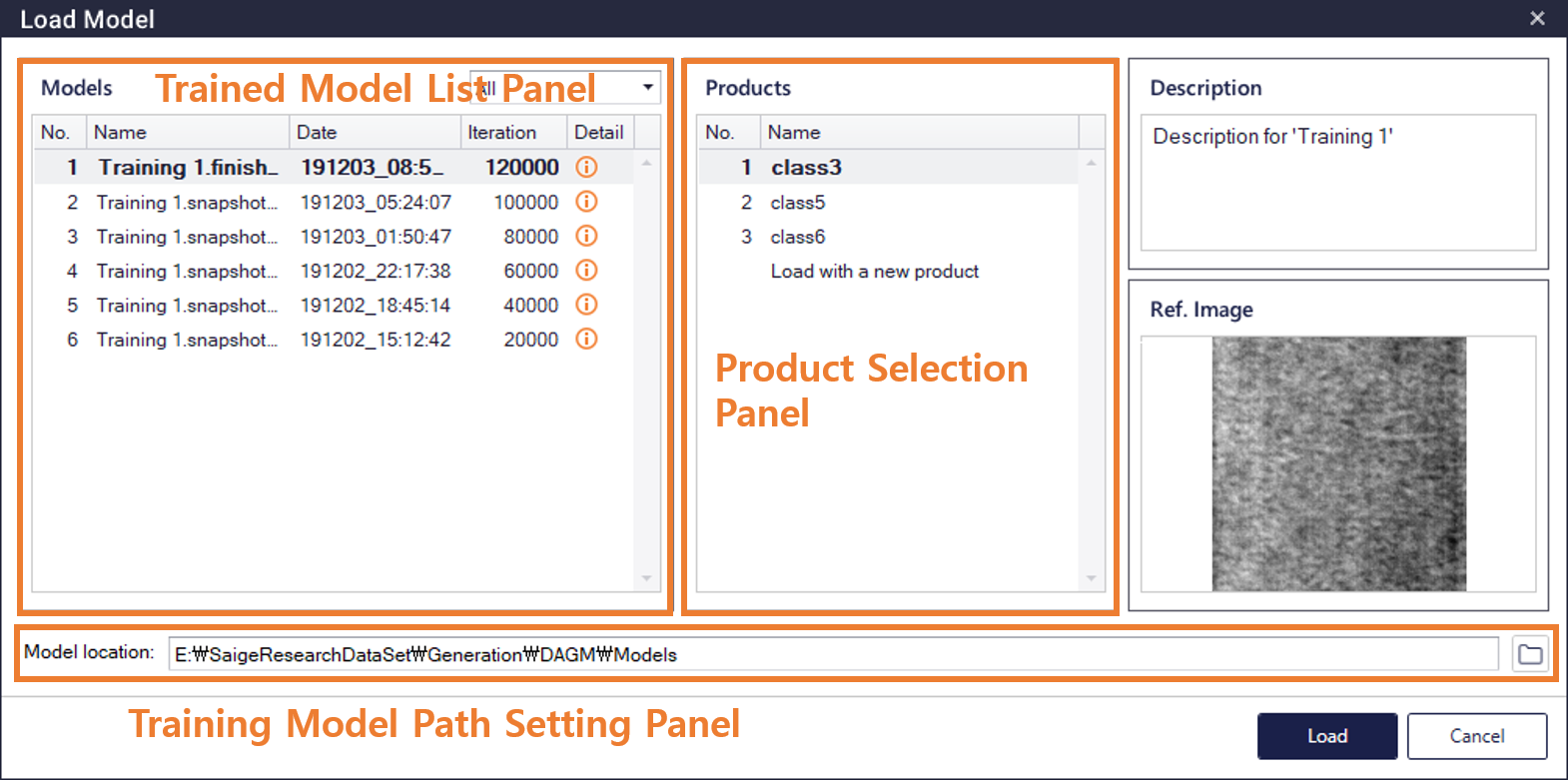
After clicking  button, users select the training model to be used in the Trained Model List panel, and then select the product to generate defects in the Product Selection panel. The Product Selection panel has a list of products used for training, and users can also select a new type of product here.
[Align] Tab
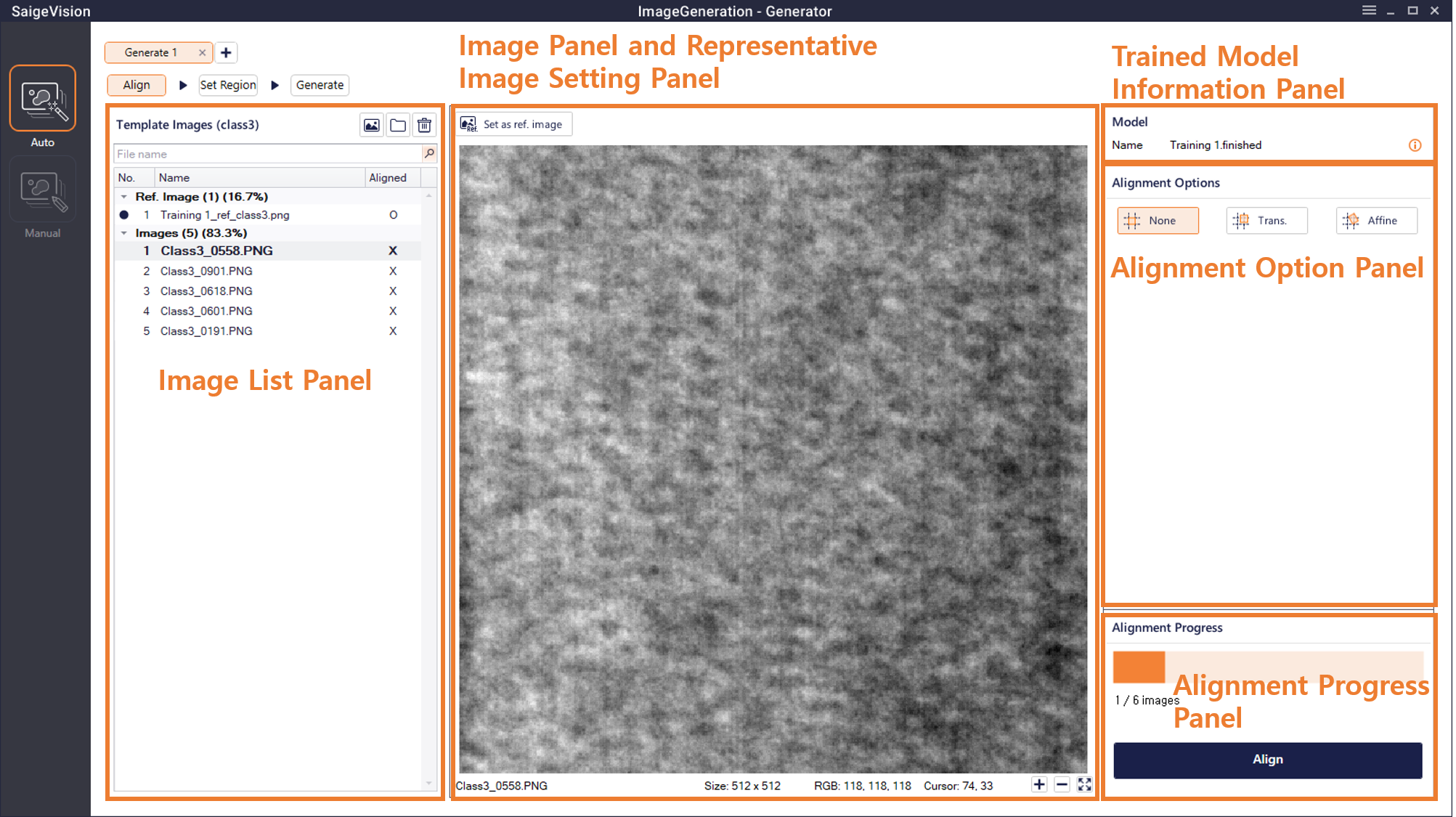
This tab loads a template image (OK image) to generate a defect and aligns the image. When the product used for training is selected when loading the model, the reference image and alignment options set during training are automatically set. User may change the reference image or alignment option; however, once it is changed, the existing defect generation region in the [Set Region] tab is reset.
When selecting a new product, users should load the template image and set the reference image and the alignment options in the same way as in Developer - [Preprocess] - [Align] tab. After setting the alignment option, users click the Align button in the lower right to perform the alignment.
[Set Region] Tab
The [Set Region] tab sets the region on the reference image where each class of defect should be generated. Each class of defect is generated in the region set in this tab.
If users selected the product used for training and didn't change the reference image or the alignment option set during training in the [Align] tab, it is automatically set as the defect generation region set in the Developer.
Defect generation regions can be freely removed, but additions may be limited by the type of defect generation region used in the Developer. The types of each defect generation region can be divided into three groups, and regions can be added only when the generation region of the group for each class is used in the Developer
| Group 1 | Group 2 | Group 3 | |
|---|---|---|---|
| Types of Generation Regions |  ,  |
 |
 ,  |
Example
If there is region drawn using
[Generate] Tab
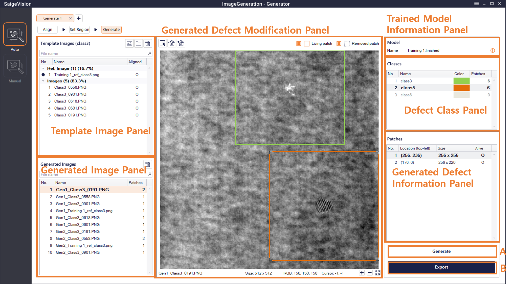
Template Image Panel (Template Images)
This shows the template image registered in the [Align] tab. Defects are generated on the template image displayed.
Generate Button and Pop-up
Clicking the Generate button brings up the following pop-up.
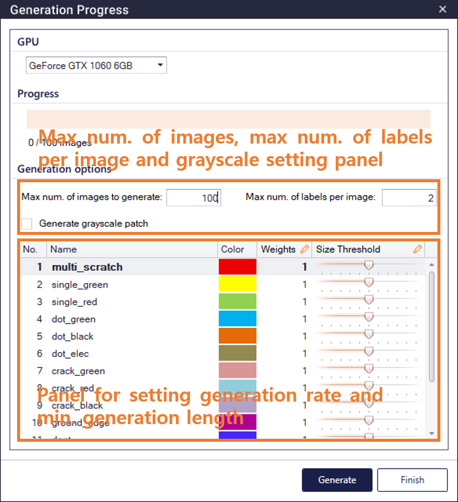
Here, users set the number of images to generate and defects, the number of images to generate in the Gray scale Setting panel, the maximum number of defects to generate per image, and whether to apply gray scale to the patch to be generated. The number of images actually generated may be less than the value of Max num. of Images to Generate. Users can set the generation rate (Weights) and the minimum generation length (Size Threshold) per class. The higher the generation rate for each class, the more defects are generated in probability. The minimum generation length is determined relative to the size of the defects used in the training. After setting Generation options, clicking the Generate button at the bottom starts generating defects.
Generated Image Panel (Generated Images)
This shows a list of generated images. The number of defects generated for each image is displayed in the Patches column.
Generated Defect Modification Panel
This shows the defects generated for each image. Around the created defect is displayed in a box shape, and when the mouse is over the box, the specific shape and class of the generated defect are displayed. The color of the box is the same as that of the corresponding defect class. Users can delete defects of poor quality among generated defects, and deleted patches are not saved when exporting the result.
 : This tool is for selecting defect patches generated.
 : This tool is for selecting a generated defect patch and then deleting that defect patch. When a defect patch is deleted, the original image is visible.
 : This is a tool to revert deleted defect patches.
 : This tool is for turning on / off the borders of the generated defect patches.
 : This tool is for turning on / off the border of deleted defect patches.
Defect Class Panel (Classes)
It shows the color of each defect class and the number of patches generated.
Generated Defect Information Panel (Patches)
This displays information about defects generated in the currently selected image (position, size, and deletion of the upper left pixel of the generated defect patch).
Save and Load Tabs
Users can save the tab which completed the inspection as a file in .srGenAutoTab format by right-clicking the tab, or clicking the Save Current Tab button in the top right menu. Saved tabs can be loaded by clicking the Add Tab button (  ), and then clicking the Load Tab button (
 ).
Export
Clicking Export button brings up the following pop-up window.
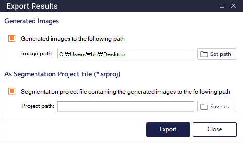
 : When this is checked, the generated defect image is saved in .srImage format in the designated path.
 : When this is checked, pixel-level labels corresponding to the generated defects are exported in SaigeVision's Segmentation project format (.srproj). Here, the deleted defect labels are not exported.