
Developer – [Database] provides the function to prepare data to be used for training. After importing images to be trained in the Image List panel, users can label the images in the [Label] tab (click the [  ] button on the top left) and divide data into Training/Validation groups in the [Split] tab (click the
 ] button on the top left). Although the information processed in the [Label] and [Split] tabs are always synchronized as shown in the Image List panel, it is recommended to proceed from [Label] to [Split].
Caution
For training, each defect class should have one or more images (in the Classification) or labels (in the Detection and Segmentation).
The following describes the detailed features and structures of each tab.
[Label] Tab
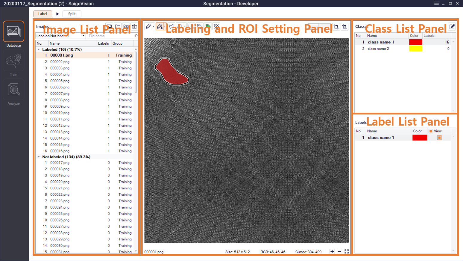
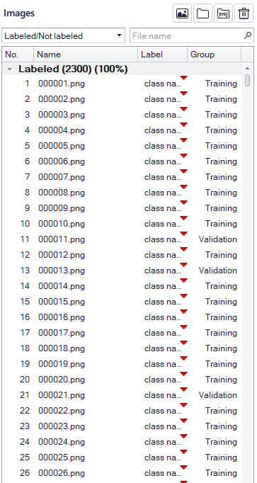
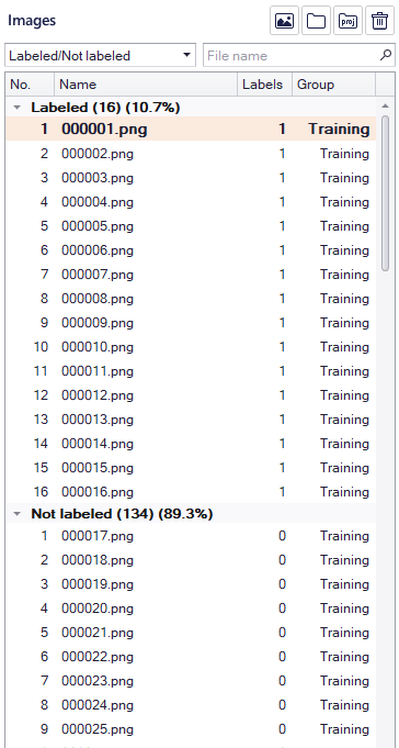
Image List Panel (Images)
Here, users can import images to work on. The information of the imported images, such as the number and name of the images, the number of labels (Labels) or label class (Label), is displayed as aligned according to specific criteria. For the Classification, the Label column shows what class the image is labeled, while for the Detection and Segmentation, the number of defects labeled in the image appears in the Labels column instead of the Label column.
 : Click here to load designated images.
 : Click here to load all images in the designated folder.
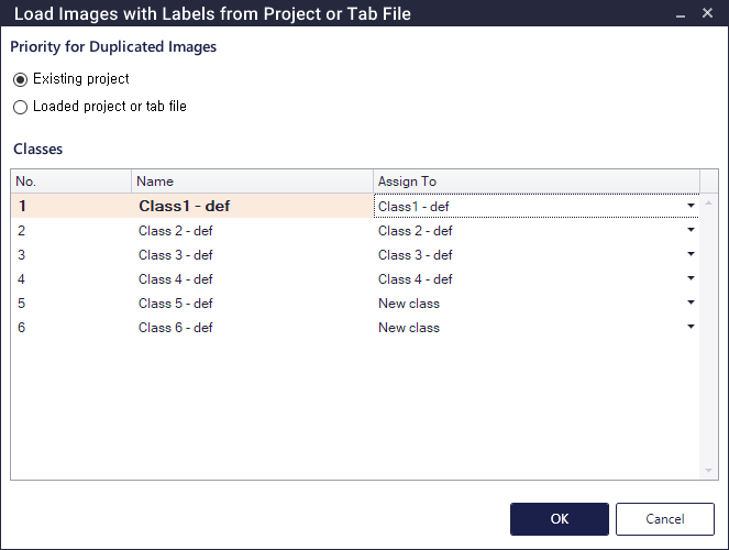
 : Click here to load images and labels from an existing srproj file. Users can also load inspection results as label information from a srAnalyzeTab file or srInspectTab file saved in the [Analyze] or [Inspect] tab. In a Classification project, only a project or tab file of the same mode can be loaded. In a Detection project, a project or tab file of the Detection, Segmentation and Image Generation can be imported. In a Segmentation project, a project or tab file of the Segmentation and Image Generation can be imported. If there are duplicate images between the existing project and the file being loaded, users can use the labels of the current project (Existing project) or replace them with the labels of the loaded file (Loaded project or tab file).
 : After selecting one or more images from the Image List panel, click here to remove the selected images from the Image List panel.
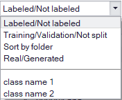
: Images in the Image List panel are aligned based on one of the following: Labeled / Notlabeled, Training / Validation / Not split, Sort by folder, Real / Generated, and Class names. : Search images by the image file name in the list.
Class List Panel (Classes)
Here, users can create and modify new defect classes. Information such as the number, name, color, and the number of labels (Labels) of created defect classes is displayed. However, for the Classification, the class for the OK image should be added to label the OK image with the corresponding class.
For the Detection and Segmentation modes, users can label the OK image by pressing  button without creating a class for the OK image.
 : Click here to open the Edit Class window where users can add and modify defect classes.
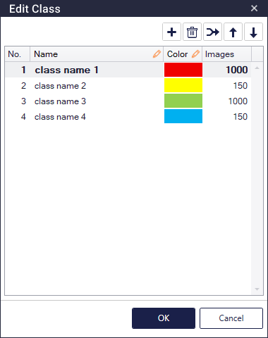
 : Click here to add a new class of defect.
- : After selecting the defect classes (multiple selection possible), click here to remove the selected defect classes.
 : After selecting multiple defect classes, click here to merge the defect classes into one defect class. The number, name, and color are maintained as attributes of the defect class located at the top of the selected defect classes.
 /
 : After selecting the defect class, click here to change the number and order of the defect class.
- After selecting a defect class, press the F2 key or double-click the name to change the name of the defect class.
- Select the Color of the defect class to change the color of the defect class.
Labeling Panel
Users can perform labeling of a selected image.
Classification
 : Click here to label the current image as the selected class in the Class List panel.
 : If the current image is labeled as a specific class, the image is changed to the Not Labeled state.
Detection
 : Click to activate the icon. Users can draw a box-shaped label by dragging the mouse cursor over the image while the icon is active. The class of the label drawn at this time corresponds to the defect class selected in the Class List panel.
 : Click to activate the icon. Users can delete defect labels by dragging the mouse cursor over the image while the icon is active. The thickness of the eraser can be adjusted by clicking
 button.
 : Click to activate the icon. Users can select (multiple) defect labels by dragging the mouse.
 : Click here to change the currently selected (multiple) defect labels to the selected defect class in the Class List panel.
- : Click here to delete all defect label information drawn on the current image and designate the image as an OK image.
- : If the current image is designated as an OK image, the image is changed to the Not Labeled state.
Segmentation
 : Click to activate the icon. Users can draw an arbitrary curved label by dragging the mouse cursor over the image while the icon is active. The class of the label drawn at this time corresponds to the defect class selected in the Class List panel. Click button to adjust the pen thickness.
 : Click to activate the icon. This has the same feature as the pen ( ), but fills the area inside the drawn label.
 : Click to activate the icon. A straight line that connects two points is drawn. Click button to adjust the thickness.
 : Click to activate the icon. Users can draw an arbitrary polygon-shaped label by clicking the image multiple times while the icon is active. The class of the label drawn at this time corresponds to the defect class selected in the Class List panel.
- , , , , : These have the same features as the icons of theDetection mode.
ROI Setting Panel
Region of Interest (ROI) Setting is a function that is used to set a specific area for inspection (Region of Interest) within an image or to exclude a specific area from inspection (blind region). : Click to make the icon active (
 ), click again to return to the inactive state ( ). While the icon is active, all images shown in the Image panel appear with the specified region of interest or blind region.
SaigeVision offers two functions: Set Simple ROI and Set Advanced ROI.
Set Simple ROI
Set Simple ROI is useful when the images are well-aligned so that the regions of interest or a
blind regions always appear at a similar size in a similar location. Click  button to enter the Set Simple ROI window.
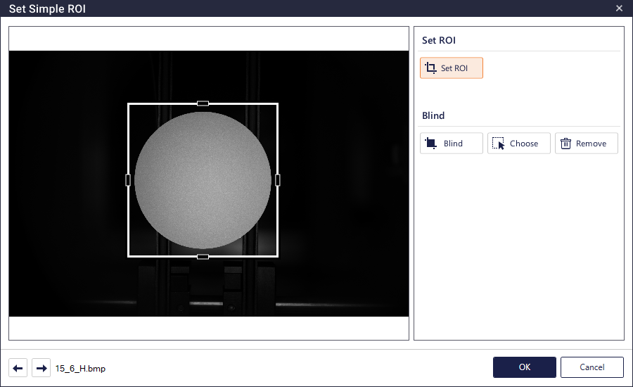
 : Click to activate the button. Users can designate the region of interest on
the left image. Regions of interest can be specified in two forms: rectangle and ellipse. The
specified region of interest is sized and positioned at the same rate for all images. For
example, when the horizontal axis of the region of interest is set from 20% to 70% of the
image width, for other images, it is set from 20% to 70% of the image width in proportion to
the size of the image. In other words, for images having various sizes, Set Advanced ROI may
be more suitable than Set Simple ROI.
 : Click to activate the button. User can exclude the area from defect inspection (blind region) by dragging the mouse on the left image. Blind regions can be set in two forms: a rectangle and an ellipse. For set blind regions, the size and position are applied in the same proportion to the region of interest in all images.
 : Click to activate the button. Users can select blind regions by dragging the mouse on the left image.
 : Selected blind regions are released.
 ,
 : Click to see the applied ROI in the next / previous images.
Set Advanced ROI
Set Advance ROI is a useful function when the size or position of the region of interest on the
image is not constant. Click  button to enter the Set Advanced ROI window.
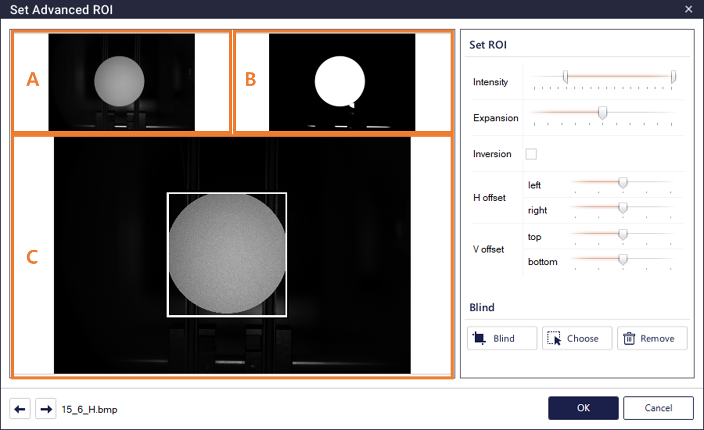
Area A shows the selected original image, Area B displays the image filtered by Intensity / Expansion / Inversion setting values, and Area C shows the image to which the final ROI information is applied.
- Intensity: This sets the maximum and minimum values of the intensity values (gray scale values) of the image pixels by adjusting the two bars on the right. In Area B, pixels meeting the ~ criteria are displayed in white, while the remaining pixels are displayed in black.
- Expansion: Expansion value can be set by adjusting the bar on the right. If the value is greater than 0, the white area of the filtered image is expanded, and if it is less than 0, the white area is reduced.
- Inversion: This inverts the black / white of the filtered image.
When both H offset and V offset values are set as default values, the final ROI displayed in Area C is designated by the box surrounding the largest white area in the filtered image.
- H offset: Users can further adjust the left / right offsets based on the ROI set through Intensity / Expansion / Inversion.
- V offset: Users can further adjust the top / bottom offsets based on the ROI set through Intensity / Expansion / Inversion.
- , , , , : Same with the buttons of Set Simple ROI
Label List Panel (Labels)
Classification
This displays the total number of images (Num. of images) loaded in the Image List panel, the number of labeled images (Num. of labeled images), and the number of unlabeled images (Num. of unlabeled images).
Detection and Segmentation
This displays information about the number, class name, color, and presence or absence (View) of the labels drawn on the image selected in the Image List panel. Whether the View checkbox is selected or not determines the presence or absence of labels on the selected image.
[Split] Tab
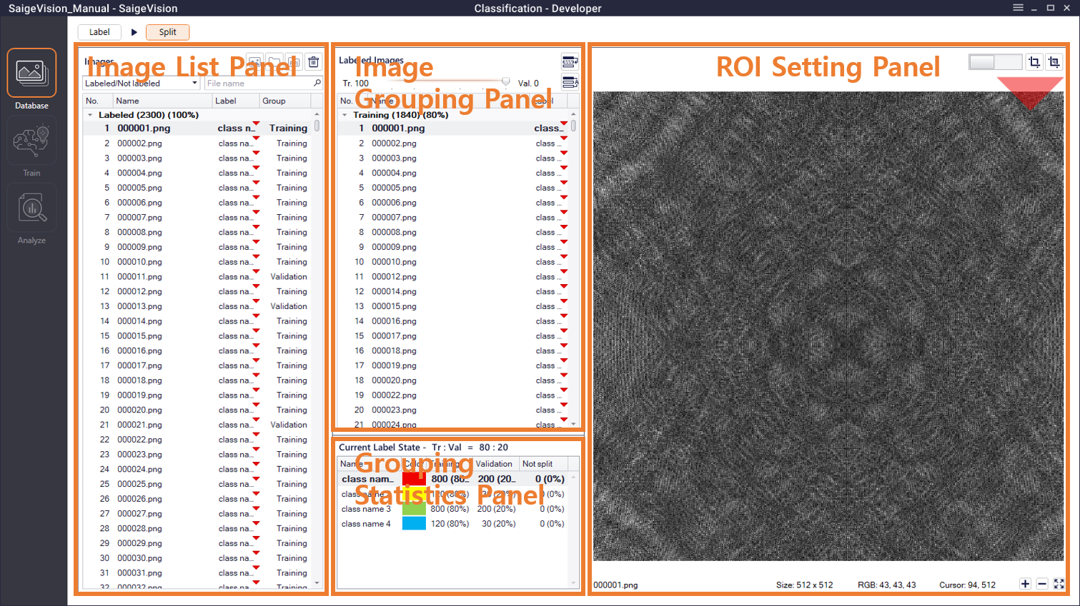
Image List Panel (Images)
This is the same as Image List Panel of the [Label] Tab.
Image Grouping Panel (Labeled Images)
Here, the images in the Image List panel are sorted into three groups (Training / Validation / Not Split). Information about the image number, name, the number of labels (Labels), or label class (Label) is displayed.
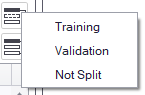
 : When users select (multiple) images in the Image Grouping panel and click this button, a window appears like the figure below. Users can select one of Training / Validation / Not Split and sort the selected images into the corresponding group.
 : Click here to automatically sort the data belonging to the Not Split group at the rate of Tr. (Training group) versus Val. (Validation group) designated in the bar on the left of the button.
- : Click here to load the srproj file regardless of its function. Each image is sorted into a group set in the srproj file to be imported. This is used to retrieve only the split information from the existing srproj.
Grouping Statistics Panel (Current Label State)
This displays information on the name, color, and total number and ratio of labels in each group (Training / Validation / Not Split) for each defect class.
ROI Setting Panel
This is the same as ROI Setting Panel of the [Label] Tab.