
The [Preprocess] tab consists of sub-tabs for aligning ( ) all the images for a specific reference image for each product with regard to images labeled in the [Database] tab, and marking (
 ) the region where each defect class mainly occurs. It should always proceed from [Align] to [Set Region], and alignment and region setting should be completed for all registered products.
The following is a description of the detailed function and structure of each tab.
[Align] Tab
The [Align] tab provides a function to align the images registered in each product.
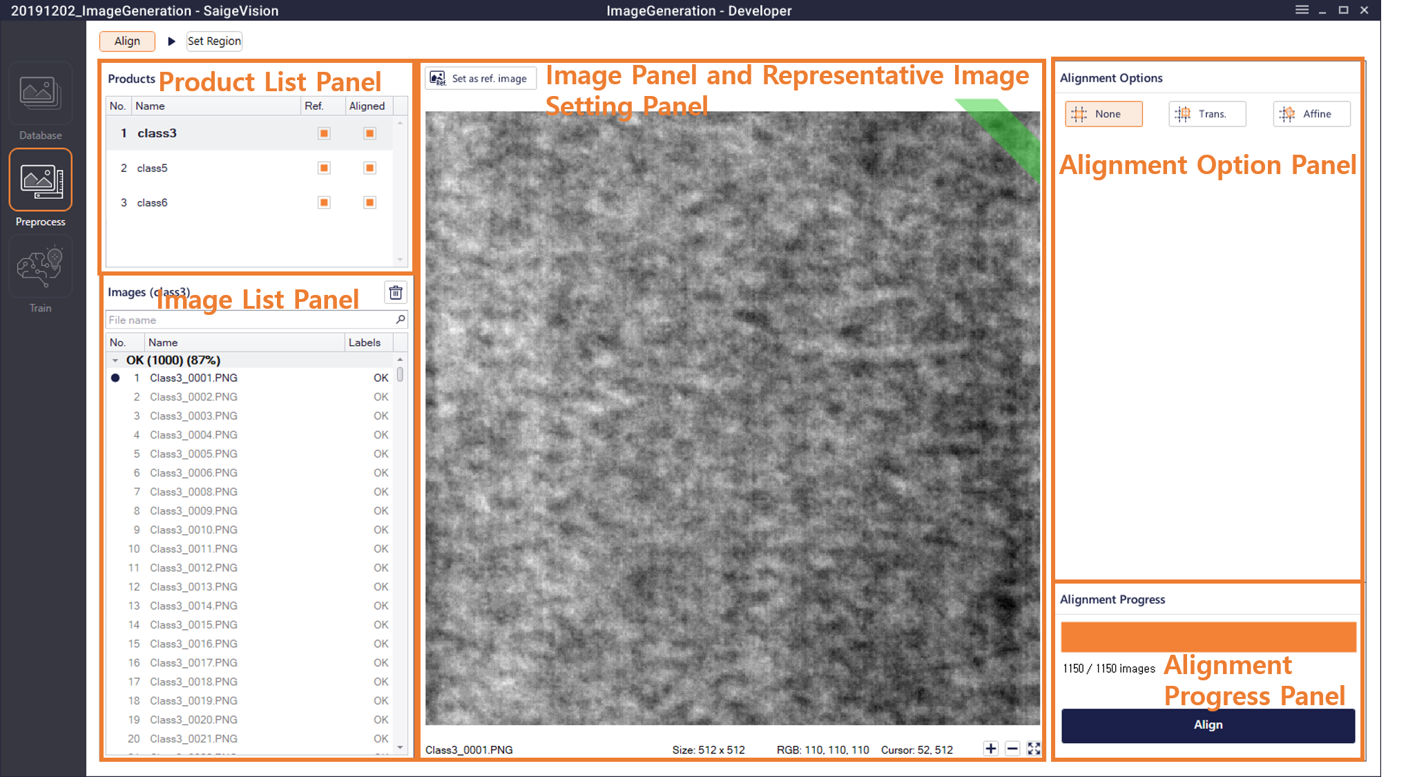
Product List Panel (Products)
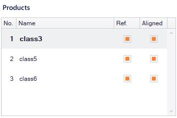
The list of products registered in [Database], and information on the setting of reference images or alignment of the images are displayed under the Ref., Aligned column (if set:  , if not set:
 ). It is possible to proceed to the [Set Region] tab only after the setting of the reference images and alignment of the images are completed for all products.
Image List Panel (Images) and Reference Image Setting (Image Panel and Reference Image Setting)
Images labeled for each product are divided into OK (image labeled normally) and Defective (image with at least one defective label). Users select a reference image that can represent the product among OK images, and then click  button in the Image panel to set it as a reference image.
Alignment Option Panel (Alignment Options)
This panel provides the alignment function required for image generation algorithms. The alignment function has three options: None for no alignment, Trans. that aligns by shifting horizontally up, down, left, and right based on a specific part, and Affine that aligns by adjusting the image's angle and size. Users should select one of three alignment options to perform alignment according to the characteristics of the image for each product, and detailed description of each option is as follows.
None ( )
This option does not compute the alignment algorithm and can be selected for products with the same or similar resolution to all images or products whose objects of interest are already accurately aligned on the image
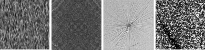
Example
The resolution of the fiber images is equal to 512 × 512. The images themselves are already aligned.
Trans. ( )
This algorithm marks specific parts or target objects that are common to all images in a box form on a reference image and then finds the exact same shape as the object displayed in the whole image to align based on it. This is used when the resolution and size of the images are all the same or similar, and the position of the object of interest in the image is horizontally shifted up, down, left, and right. Up to three parts or objects can be registered, and the accuracy of the alignment algorithm increases as multiple objects are registered.
 : Click to activate the button and display the object in the form of a box for registration. Up to three parts can be registered, and each time a part is registered, one color is added to the figure icon (
 ).
 : Click to activate the button and select the registered parts
 : Users can delete the selected part.
After the Align computation is completed, users can select an image other than the reference image to verify the parts drawn as a result of the computation and adjust the position of the part in the Image panel.
Example
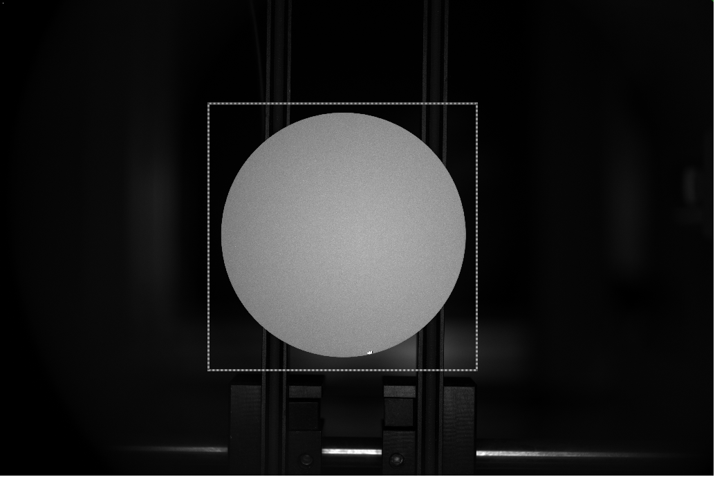
For solar panel image, in the middle of all images is a solar panel that is the inspection target, and therefore, around the solar panel is set as a reference part.
Affine ( )
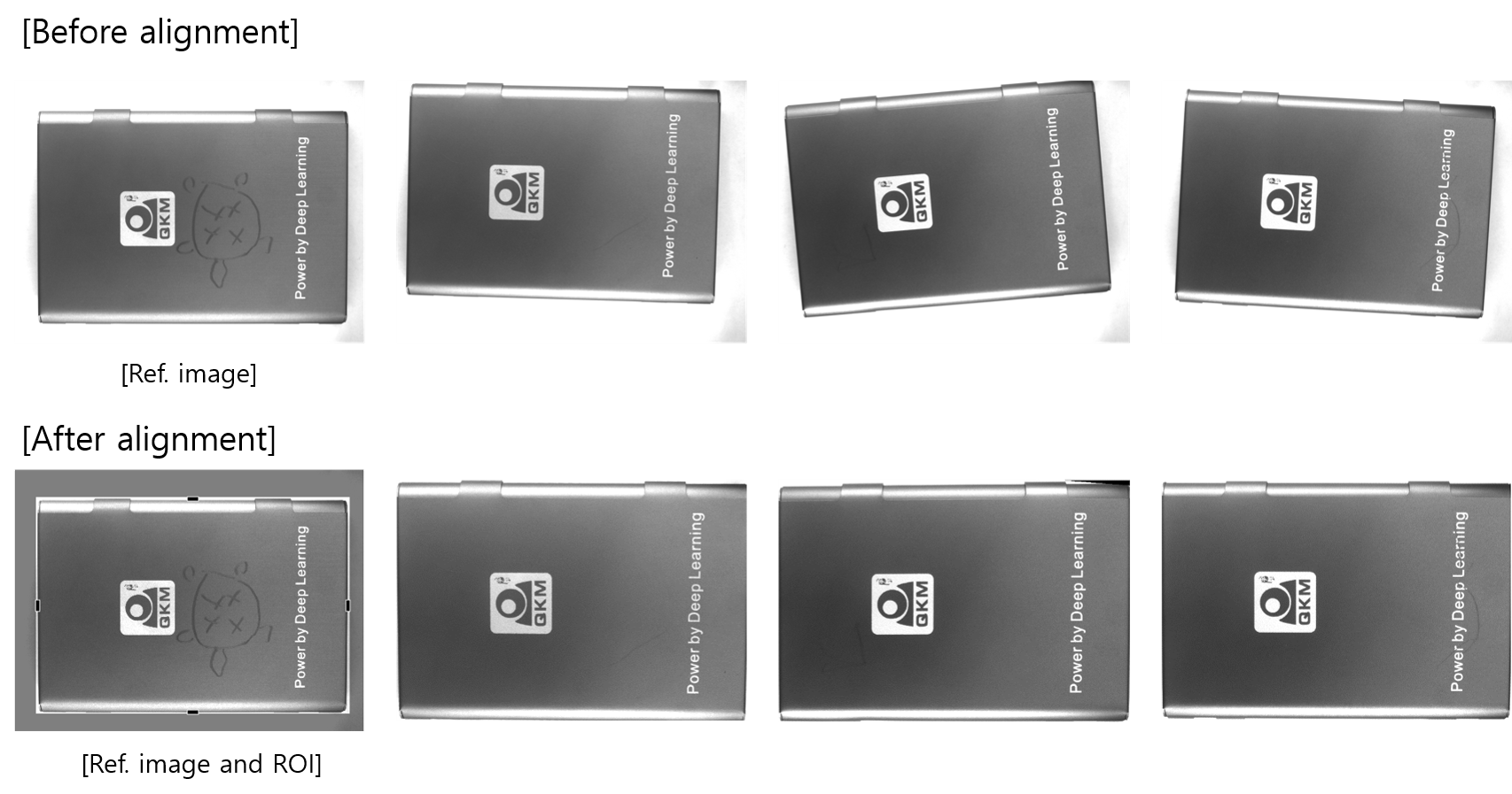
This algorithm aligns the entire image based on the reference image when the resolution, location, size, and angle of the object of interest are different. Since it is aligned based on the reference image, it is recommended to select a well-aligned image that can represent the product as the reference image.
 : This designates the region where the target object is located on the reference image.
Example
Business card case images: If the object is slightly distorted on the image, align the images by setting the ROI of the reference image as shown below.
Alignment Progress Panel
After selecting the alignment algorithm suitable for the image, users click the Align button at the bottom right to perform the alignment. The progress of the alignment is updated in real time.
[Set Region] Tab
The [Set Region] tab sets the region where defects mainly occur for each product.
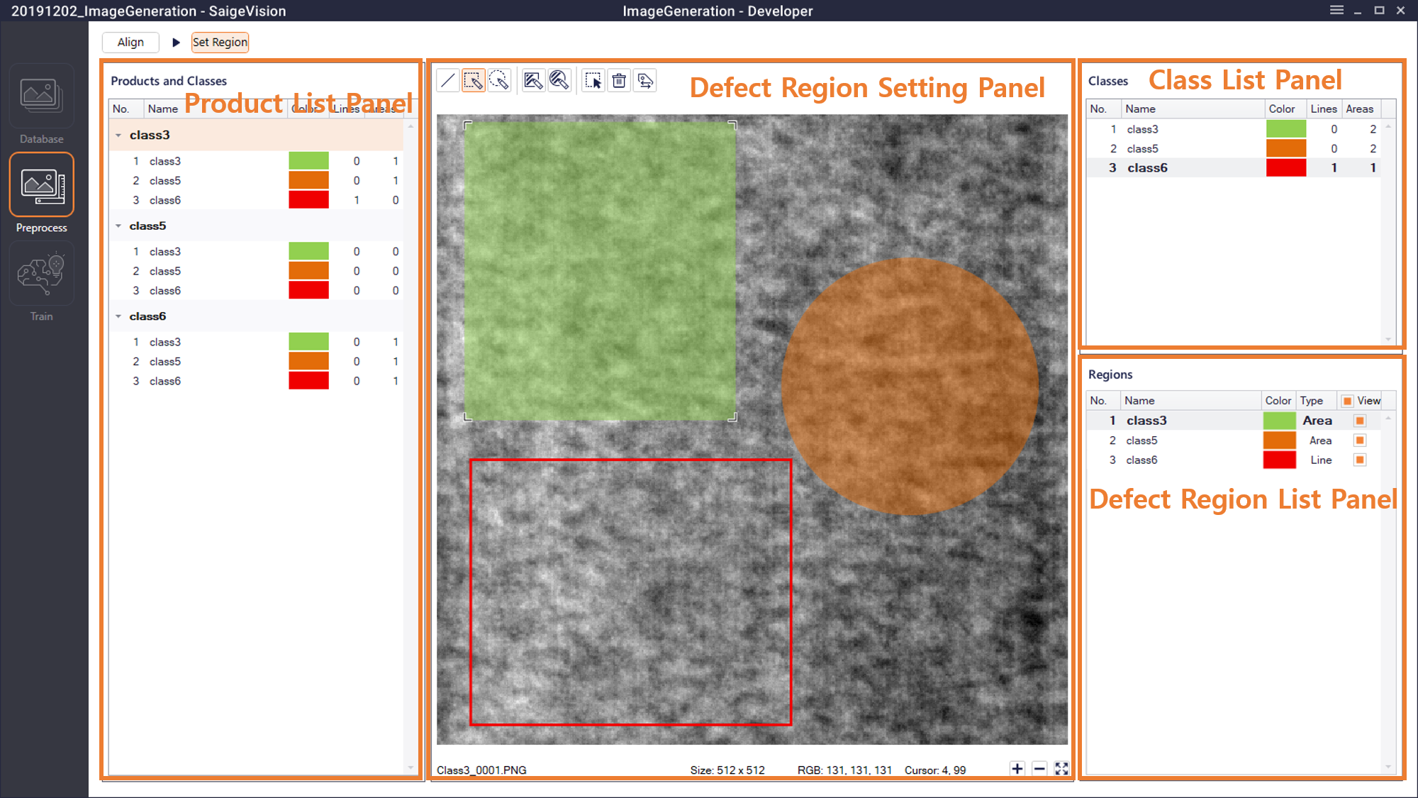
Product List Panel (Products and Classes)
This panel shows defect region information registered in the reference image for each registered product. Clicking the name of the registered product displays the reference image of the product in the Image panel on the right.
Defect Region Setting Panel and Class List Panel (Classes)
This panel sets the location and characteristics of regions where defects occur on the reference image of each product. When users select a defect class in the Class List panel, the Defect Region Setting panel on the left shows the region where defects mainly occur for each defect. Defect generation is trained along the set region.
Users can adjust the position of the selected area while  tool is selected among the drawing tools.
Line Type Defect Region (Line)
This function displays information about defects occurring on a specific line, such as broken edges.
 : This sets the region where the defect occurs as a straight line.
 : This sets the region where the defect occurs as the corner of the rectangular box.
 : This sets the region where the defect occurs as a circle border.
Area Type Defect Region (Area)
This function trains so that defects can occur anywhere within the set area.
 : This sets the area where the defect occurs as the inner region of the rectangular box.
 : This sets the area where the defect occurs as the inner region of the circle.